Well, I have started into my basement shower remodel. I would like to maintain as much shower space as possible. One wall is a concrete wall. No sign of moisture migration. I am going to apply a latex vapor barrier material as a precaution. I was planning to fasten furring strips to the cement and then screw my moisture-resistant S/R to the stips, but I would prefer to adhere my moisture-resistant sheetrock directly to the cement wall.
I decided to use the furring strips, partly because it will allow easier installation of the shower head plumbing. I won’t have to make a notch in the concrete wall for the piping. I will be using a product called Dryloc on the concrete wall, just as a precaution. When I tore out the old tile shower the mud scratch coat was applied directly to the cement. I saw no evidence of moisture but I just want to be sure.
I certainly appreciate the hydroban, cement board, mesh tape in thinset and more hydroban, especially if I were doing ceramic tile again where moisture could still get through the grout lines. In this case, the walls will be seamless solid surface. I just need a surface to attach the panels to.
The existing shower was cultured marble that installed 24 years ago. I got tired of having to strip out the silicone and re-caulk every couple of years. It was 34″ x 42″.
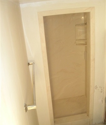
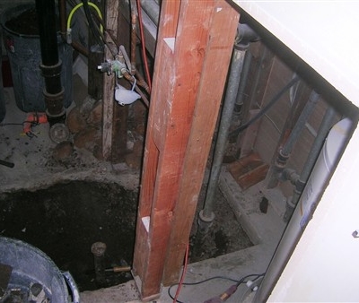
Under the cultured marble was ceramic tile with mud and metal lath. No shower pan liner. I guess the figured they didn’t need it since they were on concrete in the basement. Cast-iron drain stack from the upstairs bathroom. Notice the cleanout facing the shower. That is why the shower was only 34″.
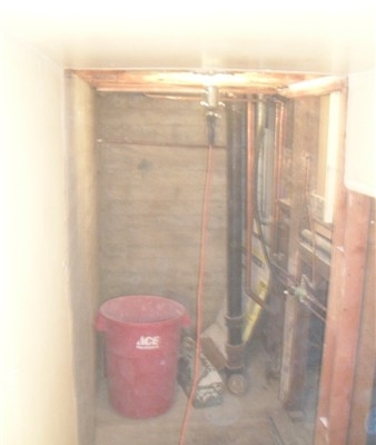
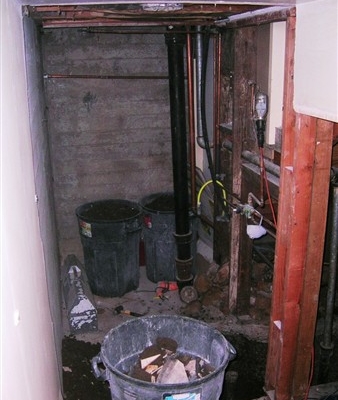
Last December the water heater developed a leak. It was located where the trash can is now. It was very difficult to gain access to and service so I moved it far to the right (out of this photo) under a stairwell.
The old drain was about 3″ from the existing tile wall. I wanted it moved more toward the center of the shower. Also at the far right of the photo, you can see a cast iron vent pipe that is right in the middle of the floor space of what could be nice storage area under an existing stairwell…bummer. That vent is going to move.
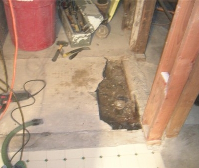
Now that I have dug down to the old piping I can see what needs to be done to get what I want.
I capped off the vent pipe and ran a new one so that it would be inside of the wall. New drain and P-trap near the center of the shower area. Now I am happy. The vent pipe under the stairs has annoyed me since we bought the house 24 years ago.
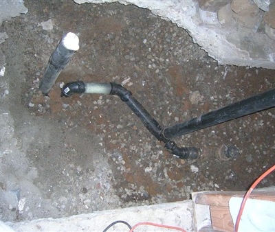
I didn’t get a photo but I also replaced the cast iron drain stack and installed a new cleanout 90 deg. left so that I could push the shower right up against the stack for more room. It’s finished size will be 42-1/2″ x 53″.
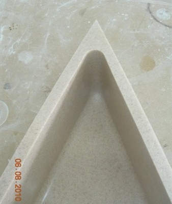
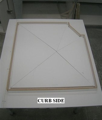
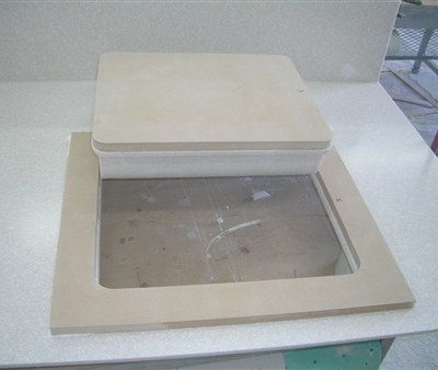
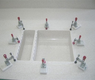
This is the form for thermoforming the floor. It has a 5/16″ pitch slope to the drain. The outside perimeter of the form is spaced away from the floor so that I can make the solid surface pieces slightly oversized. The perimeter pieces of the mold 1/2″ higher than the floor of the mold so when I apply the vacuum blanket it would curl down the edges.
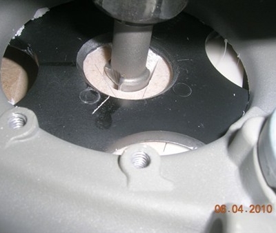
After thermoforming and trimming the floor to the exact size I cut a piece of particle board so that it was 1″ smaller than the finished floor. Then a 1″ collet and a 3/4″ bit is used to go around the edge to make a 1/8″ x 7/8″ rabbet for the cove build up strip.
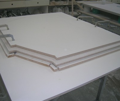
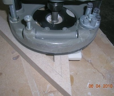
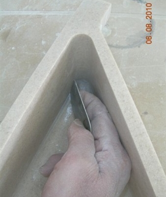
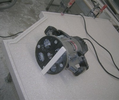
The pan is pre-coved before adding the apron around the sides. A 3/4″ core box bit is used with a fence attached to the base. I actually have a bonafide router fence but it takes longer to set up than just hot melting a temporary fence directly to the base. Set the router to that is just a sliver above the surface of the sloped floor and run the router around with the fence to the outside of the pan.
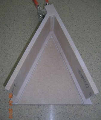
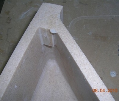
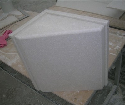
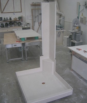
I pre-made the corner seat. The outside corners are V grooved beveled on the table saw. It is not done yet in this photo but I also pre coved the seat before assembly.
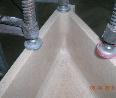
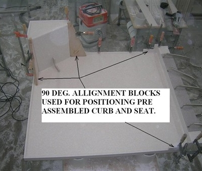
OK, I am busted. I have a bit of a mess going on around the work area. Here I am attaching the corner seat and the pre-made curb (front top and inside face). The top of the curb has about a 1/4″ slope on a 4″ width.
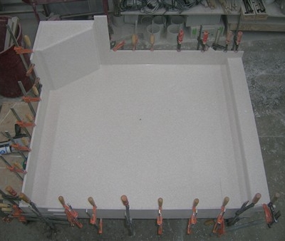
I added an apron around the sides and also on top of the corner seat so that when I glue the wall panels in place I won’t have to deal with the cove area. Oh, I forgot to mention that when this shower is finished it will be totally coved. The only place that will have a caulk line is at the ceiling.
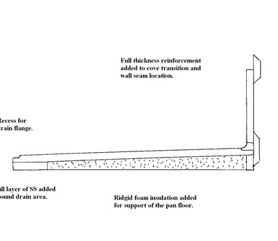
The last part of the pan assembly was adding reinforcement at the cove transition area and the joint where the walls would seam to the pan. I didn’t get a photo of that but this cross-section drawing will give you the idea.
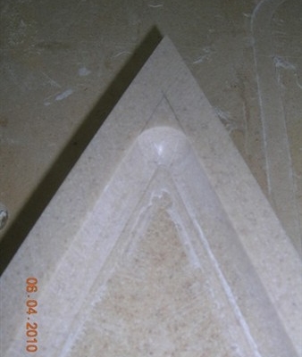
The cove detail was done with the single rabbet technique. I thought that it would be advisable to add reinforcement there.
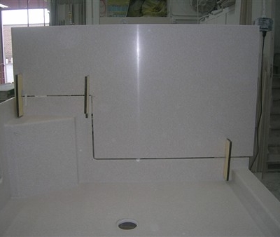
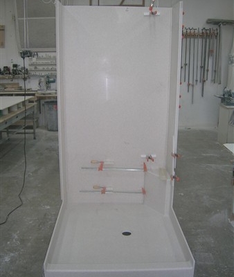
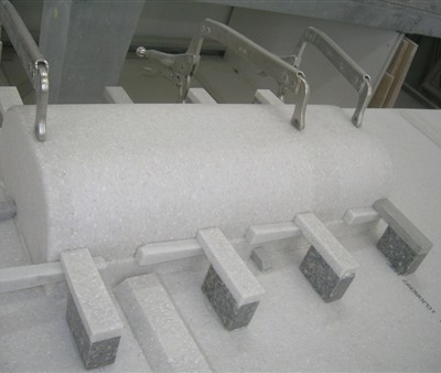
Because the wall sections would be too large to handle, I set the lower section of the walls in place, prior to fabrication of the whole wall, leaving a 3/8″ gap. This was to allow me to do a mirror cut on the entire seam including the step up to the seat. I secured them into position with spanners using hot melt. The spanners have a relief cut in them for the router bit to pass.
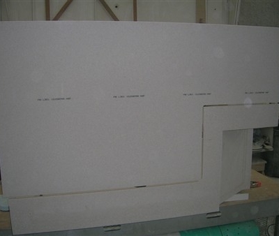
This is the backside of the wall. Straight edges above the seat and to the left of the vertical seam were set up so a 1/2″ bit through starting at the far right and stopping at the bottom corner. Then a straight edge was added below the bottom seam and stopped the router at the right corner. With care, you can get the stopping points to be very close. The inside corners needed to be hand fit with a sanding block to fit the radius of the cut made by the router bit at the outside corners.
Once all the bottom sections of the walls had been fit to the pan I completed fabricating the walls. The space for the walls was templated so that the walls, when finished, would match in size and squareness to the space they were to be installed. I needed to have a vertical site seam on each wall. I made each section 1/2″ wider than needed and then ran a 1/2″ bit through the seam location to cut the panels and create the perfect seam.
I didn’t want any of my site seams to be at the coved corners. I made all the wall seams at least 6″ from the corners.
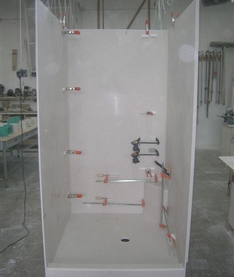
The first piece is dry-fit to the pan. All wall seams have a seam strap. The coves on the walls were done with the double rabbet technique. That was in order to have overlapping joints in the cove detail. I believe this will be enough reinforcement at the verticle wall coves. In this photo, the pan does not have the reinforcement pieces added yet.
This is the second piece in the dry fit.
All the walls are now dry fit. I wanted to dry-fit the walls before adding the reinforcement to the pan just to be sure that they would sit flush or even slightly less than flush at the apron around the pan. If the walls were even the slightest bit larger it would be impossible to install them after the reinforcement was in place.
Now to really add the WOW factor to the shower I added two integral soap/shampoo caddy’. His and hers, ya know? Hers was W12-3/4″ x H17″. Mine was W8″ x H17-3/4″.
A 1/2″ core box bit was used and a slotted jig that was cut as a ramp to rout the tapered grooves. I was surprised that it really didn’t leave much of a line in the center of the grooves.
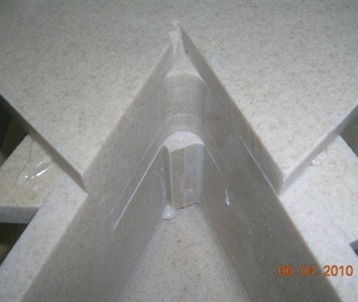
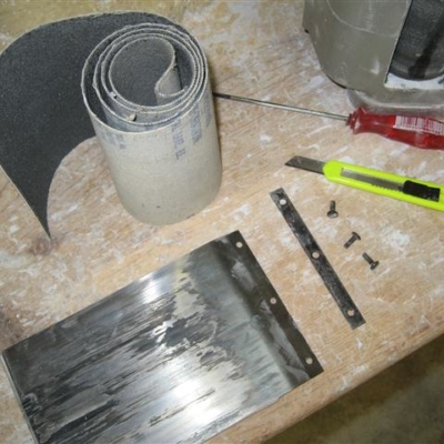
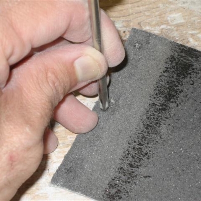
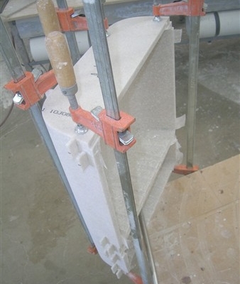
I dry fit and clamped all the parts together, aligning all the coves as flush as possible. After sanding the back of the parts completely flush, I used 1/8″ wide pieces of SS to make small overlapping alignment fingers. These were super glued on opposing sides of the joints to assist with aligning all the parts while gluing. 1/8″ pieces were used so that they would break off easily after gluing. These pieces act just like the alignment fingers on an expandable dining table.
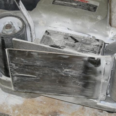
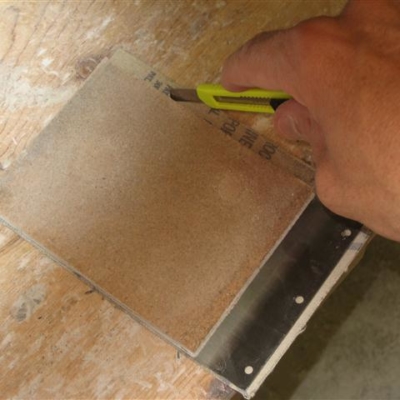
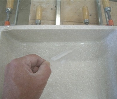
You may have noticed in the first photo what appeared to be cellophane tape. I applied this at all the seams and trimmed it flush prior to gluing together. Once all the parts were glued together Using a gloved finger I thinned down the glue squeeze out to just a thin film. When it was soft cured I peeled the tape off. The result was a minimal glue line to finish off.
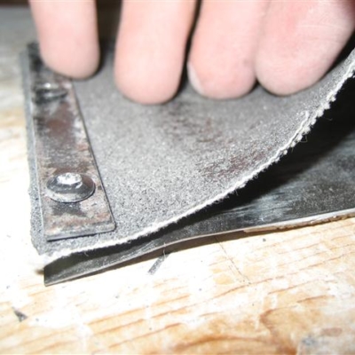
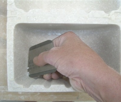
The minimal glue line and any parts that weren’t quite perfectly flush was easy to scrape down with a scraper. (Standard cabinet scraper cut in half at an angle and rounded on the corners).
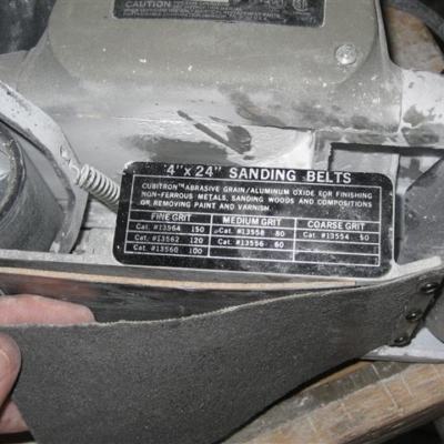
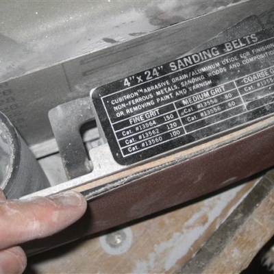
I did as much finish sanding as possible before gluing to the wall panel. It was much easier to sand when I could hold it on the table and spin it around as needed as opposed to sanding it after it was installed in the center of a panel.
The small caddy was simply glued to the back of the wall panel. Because the sides of the caddy are angled, I could run it through the tablesaw (backside down) to create a narrow ledge. I used clamping blocks hot melted to the back of the panel and wedges to gain pressure against the narrow ledge.
After the adhesive was set I used a velvet guide trim bit to trim it out on the front side. this wouldn’t make it flush of course because of all the angles. I did some experimenting and finally used a 3/8″ standard flush trim bit in my laminate router. I used it freehand so that I could visually match the angle of the sides and the grooves. It worked pretty darn good and left minimal sanding.
For the large caddy (hers).I decided to try mounting it like a bevel plug or a bevel mounted sink. For the future, I can use this and make a glacier white (or other colors) caddy and insert it into a contrasting color panel leaving a 1″ border around the caddy. I could also install a caddy after the fact in a pre-existing shower wall.
I made these hold down clamps that are hot melted to the wall panel. This help makes sure that the bevel seam is tight everywhere.
Sand it flush and move on to finish sanding.
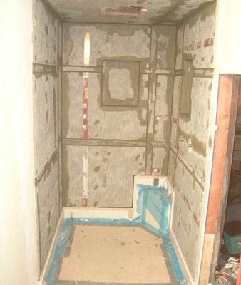
Shower pan and concrete backer board going in:
Notice the cleanout on the 4″ standpipe. that was part of the reason for the corner seat. The cleanout encroached into the shower area. I really didn’t want to dig up that much more concrete so I added a new cleanout 90 deg left just above the old cleanout. (After this photo was taken).
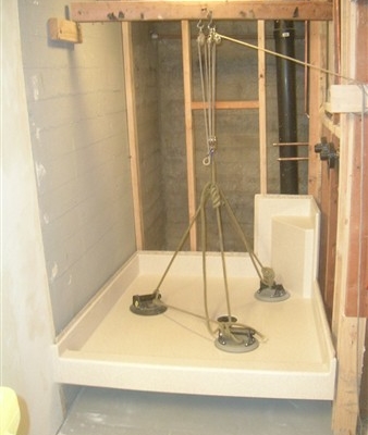
I moved the drain near the center of the floor. Leveled new concrete and installed two new shower valves and heads.
The pan was heavy and I used a makeshift block and tackle system for lowering it into place. The pan needed to be placed before all the concrete backer board was installed.
Backer board installed and mudded.
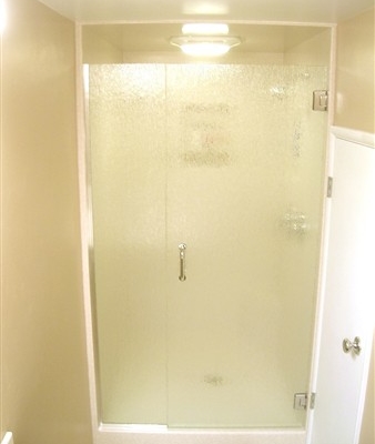
I finished up by installing the walls and sanding everything smooth. A glass shower door was added and the project is now complete.
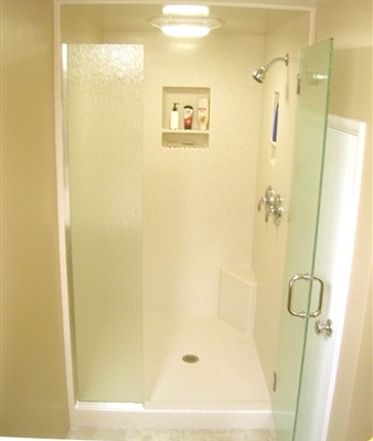
The most challenging aspect of this remodel was incorporating the seat and pan with the seamless design of the shower walls. Without the integral seat it would have been much easier. But the seat was necessary to avoid an existing plumbing cleanout. Besides, I embraced the challenge.
Author, Fabricator, and Installer – Johnny Cristensen at Solid Surface Technologies
Facebook: http://www.facebook.com/SolidSurfaceTechnologies
PHOTO COURTESY: JOHNNY CHRISTENSEN @ Solid Surface Technologies